3D Cone-Beam CT Reconstruction
This tutorial explores a challenging 3D inverse problem using the Walnut dataset. Reconstructing 3D volumes is computationally intensive and memory-demanding, making it a prime candidate for distributed solving.
The Dataset: Walnut Cone-Beam CT
What is it?
The dataset consists of X-ray Computed Tomography (CT) data of a walnut, using cone-beam geometry. A point X-ray source emits a conical beam that passes through the object and is recorded on a 2D detector, producing projection images from multiple viewpoints. The task is to reconstruct the full 3D volumetric structure of the walnut from these 2D projections. The underlying volume is derived from a real CT scan, with cone-beam measurements generated using a physically realistic forward model.
Real-world analogy: Similar to medical CT scanners or airport baggage scanners, where a dense object with complex internal structure is reconstructed in 3D from multiple X-ray projections.
Dataset Preview
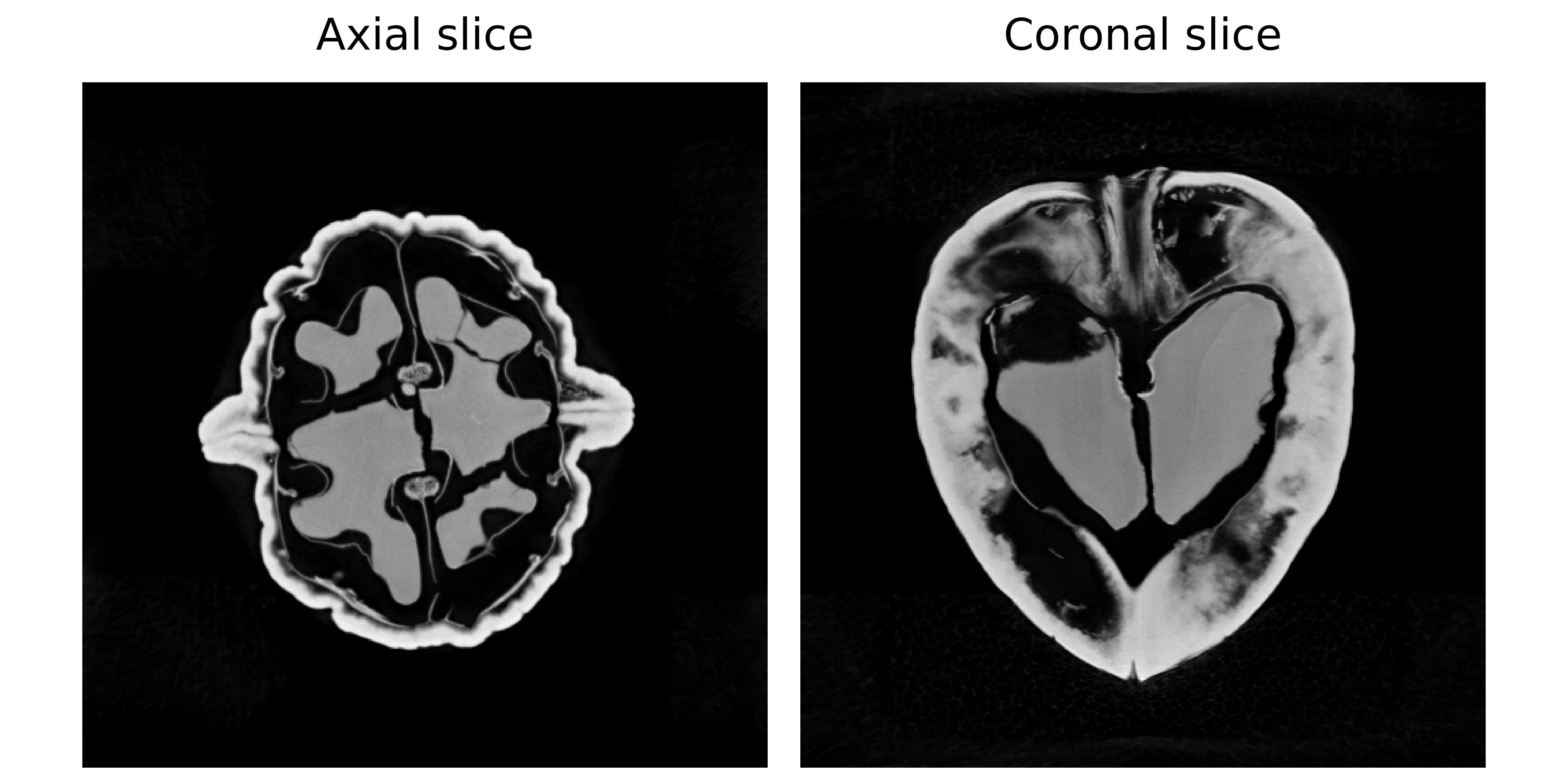
Left: Axial slice (horizontal view from above) Right: Coronal slice (vertical view from front).
Configuration: Experiment Setup
Benchmark Purpose
The primary challenge in 3D CT is GPU memory management. A 3D volume and the associated denoiser network operations can easily exceed the memory of a single GPU.
This experiment focuses on optimizing distributed parameters on a multi-GPU setup. Specifically, we investigate how the max_batch_size parameter affects performance and memory usage when running on 2 GPUs.
We use the configuration file configs/tomography_3d.yml.
Execution Grid
All runs use 2 GPUs but vary the batch size used during the distributed denoising step:
slurm_gres, slurm_ntasks_per_node, distribute_physics, distribute_denoiser, patch_size, overlap, max_batch_size, denoiser_sigma, denoiser_lambda_relaxation: [
  ["gpu:2", 2, true, true, [8,256,256], [2,16,16], 10, 0.03, 10.0],
  ["gpu:2", 2, true, true, [8,256,256], [2,16,16], 8, 0.03, 10.0],
  ["gpu:2", 2, true, true, [8,256,256], [2,16,16], 4, 0.03, 10.0],
  ["gpu:2", 2, true, true, [8,256,256], [2,16,16], 2, 0.03, 10.0],
]
slurm_gres: gpu:2: All configurations use 2 GPUs.distribute_physics: true: Projections are split across GPUs.distribute_denoiser: true: The 3D volume is split into chunks (patches).patch_size: [8,256,256]: The size of 3D patches processed by the denoiser.max_batch_size: Controls how many patches are processed in parallel on each GPU. Values Tested: 10, 8, 4, 2.
Why vary batch size?
Processing more patches at once can sometimes speed up computation, but it also increases memory usage, and a batch that’s too large may cause an Out-Of-Memory (OOM) error.
Dataset Parameters
dataset:
  - tomography_3d:
      num_operators: 2
      num_projections: 50
      geometry_type: conebeam
      use_dataset_sinogram: true
num_operators: 2: Number of tomography operators (angle splits).num_projections: 50: Number of projection angles to use.geometry_type: conebeam: Projection geometry for ASTRA.
Solver
We use PnP with a 3D-capable DRUNet denoiser, initialized with a Pseudo-Inverse method:
solver:
  - PnP:
      denoiser: drunet
      init_method: ["pseudo_inverse"]
Interpreting Results
Benchmark Results
Below is an interactive dashboard comparing the configurations:
Interpretation
Batch Size vs. Memory
Peak GPU memory grows with max_batch_size, so smaller batches are needed when memory is limited to prevent OOM errors.
Batch Size vs. Time
Larger batch sizes are usually thought to speed up denoising by making better use of GPU parallelism, but that doesn’t always happen. The effect depends on the denoiser model, image size, and chosen batch size. For more details, see the takeaways page.